Electrical Junction Box Layout with Terminal Details AutoCAD DWG
Description
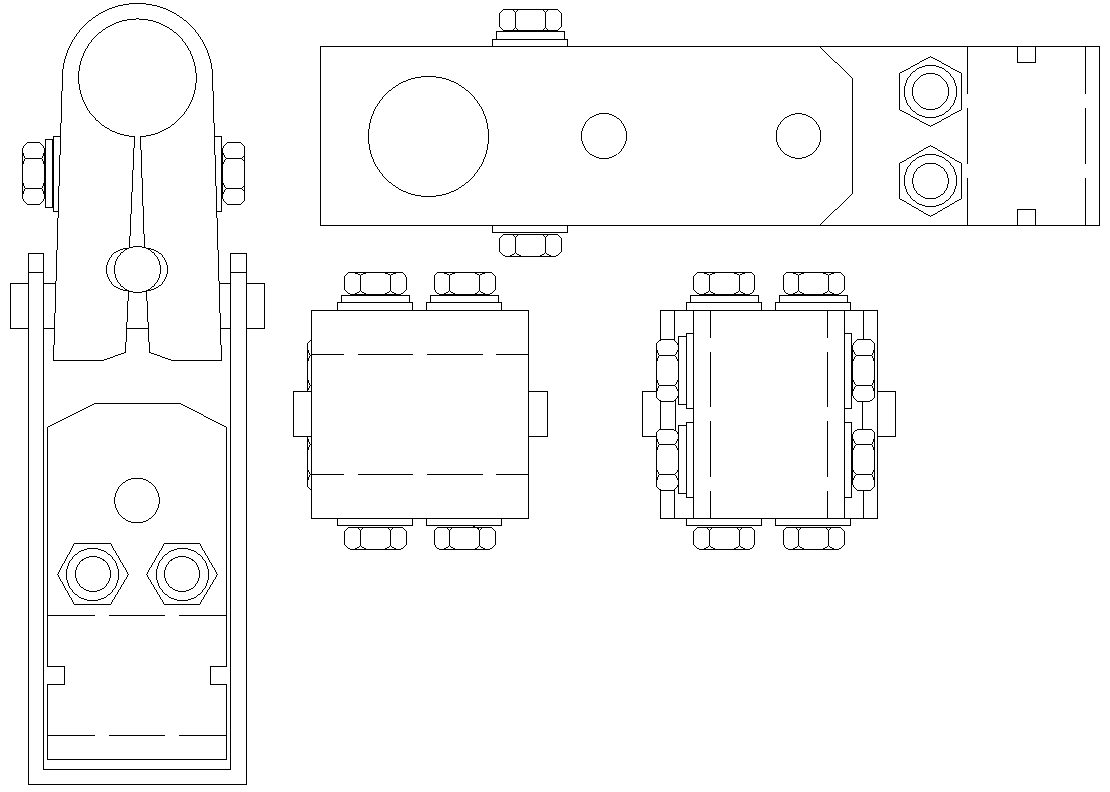
This electrical junction box layout AutoCAD DWG drawing provides a detailed representation of a junction terminal box used in electrical installations. The drawing includes multiple orthographic views, such as front, top, and side elevations, to clearly illustrate the enclosure form, terminal positioning, and internal connection arrangement. Bolt and nut locations, fastening points, cable entry openings, and terminal alignment are accurately shown to support proper assembly and secure wiring. The layout reflects precise spacing and symmetry to help users understand how electrical conductors are routed and terminated within the junction box. Clear outlines and standardized drafting practices make the drawing easy to interpret for planning and execution purposes across different types of electrical projects.
This junction box CAD drawing supports accurate electrical planning by providing clear guidance on component placement and connection flow. It helps reduce installation errors by clearly defining fixing points, enclosure dimensions, and terminal access areas. The scalable DWG format maintains clarity at all zoom levels, allowing detailed review of connection zones and fastening arrangements. Suitable for residential, commercial, and industrial electrical works, this drawing acts as a reliable reference for fabrication, coordination, and installation. It assists professionals in achieving safe, organized, and efficient electrical connections through precise and well-structured layout information.
File Type:
DWG
File Size:
45 KB
Category::
Electrical
Sub Category::
Architecture Electrical Plans
type:
Gold

Uploaded by:
Eiz
Luna
